One important purpose of this project was to make my own electronics. I wanted to do it from the very beginning: selecting components, designing, testing, designing the PCB-layout and finally manufacturing the boards, at least once. Therefore I started scanning the net and other sources for miscellaneous processors and solutions. It had to be cheap, fairly simple and common. The development tools had to be available and free (or at least cheap) too.
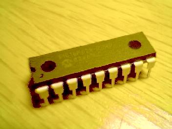
I finally selected the popular PIC16F84 processor from Microchip. I'll eventually replace it with the enhanced PIC16F628.
|
These processors are small and fast one-chip processors with flash memory, interrupts, timers, many digital and analog I/O:s et c. The simplicity and low price in combination with the free simulator/assembler/debugger MPLAB and excellent documentation has made them popular among hobbyists. And I like them too, I just wish they had more memory...
All on-board electronics is currently based on the PIC16F series.
For several reasons I chose a general, hierarchical and modular approach. I wanted to be able to reuse everything in this project in future projects. Actually, this is a whole project itself. The system can constitute a multiprocessor system based on e g the PIC16F628 processor for almost any purpose!
On board the robot there will be a PCB I call the hub. It is responsible for receiving/transmitting messages in the system to/from the destinations/sources over the nibble bus that connects all modules. It is connected to e g a PC via the standard RS-232 serial port and can also act as a command interpreter.
The hub will be able to connect to at least four but perhaps up to eight application PCBs such as servo PCBs or sensor PCBs (or external memory PCBs, or a sensor PCB, or ...). The application PCBs are on board the robot too. Since the current servo PCB can control up to eight servos each, the system could theoretically control 64 independent servos (and actually receiving 16 digital input signals since each servo PCB can manage two digital signals). But it should be possible to connect several hubs to each other too so the sky's the limit :)
 |
I plan to replace the hub processor in the future with a direct connection to a more powerful on-board robot computer. The robot computer will be able to calculate the robot movements et c on-board and in real-time and also process sensor input, thus making the robot more autonomous. For the moment all intelligent calculations will be done by an ordinary off-board PC.
The minimal configuration will be one hub with three servo PCBs connected to it. The hub will be connected to a PC via the RS-232 port. This will make it possible to control up to 24 servos (18 needed) and receiving six digital input signal (preferrably indicating foot contact with the ground).
To minimize the execution overhead in each PCB (especially the servo PCBs since they must produce time-critical pulse-width-modulated signals for up to eight servos) I had to make communication efficient. An important complication was that the PIC16F84 I originally designed the system for, had NO hardware support for communication - everything had to be done in software.
In order to achieve smooth and synchronized robot movement, the flow of servo angles must be high and distributed "simultaneously" to the servo PCBs.
Hence, I developed the half-duplex nibble bus. It allows fairly large amount of data to be sent at as high speed as the busiest processor on each end allows. All PCBs are connected to the hub, which is the bus master, via the nibble bus. Only one PCB talks to the hub at each time. The hub selects who to talk to and the direction of the data flow on the bus.
The idea was to send fast bursts of information to each servo PCB (or any application PCB) in order to let the servo PCB spend as much time possible on pulsing the servos. The PC, on the other hand, sends data in an even data stream on the serial line.
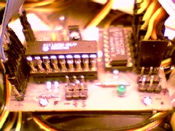
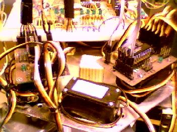
The hub is a double-sided PCB that controls three servo PCBs at this time. It is driven by a PIC16F628 processor. The processor runs at 20 MHz and utilizes the hardware support for serial communication. For the moment it talks to the PC with 19200 baud which seems quite enough.
 |
 |
 |
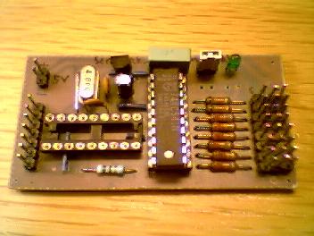
There are three LEDs that indicates, in binary code, which PCB that's active on the communication bus. There are currently two pins left unused. One of them will be connected to all connected PCB's master-reset pin in order to reset them by hub software.
The design principle was thoroughly tested in a test circuit before the PCB layout started. Most IC capsules are actually only current limiting DIL resistors to protect the hardware from e g software bugs.
The brown cable is the power line to the entire robot. The gray flat cable to the left is the RS-232 line to the PC. The gray flat cables to the right are power lines and the nibble bus lines to the three servo PCBs.
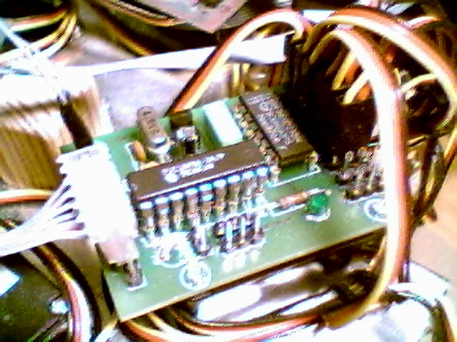
The servo controller was the first piece of electronics I developed in the project. It consists of a PIC16F84 processor, a demultiplexer, some oscillator circuitry, a voltage regulator and connectors. It can control up to 8 RC-servos through pulse width modulation. This, as all future application cards, is a stand-alone card that can run completely independently if programmed to.
The servo power lines are connected directly to the input power whilst the PCB itself gets stabilized 5V maximum. This enables higher voltages than 5V to be supplied to the servos without harming the electronics.
Two digital I/O pins are available. They will be used for sensing when each foot has ground contact.
There is a heart-beat LED present that is the PCBs interface to the outside world (not counting the nibble bus).
This PCB has been developed in three "suites". The very first (v1.0-1.1) was more or less only an attempt to get the process to work: designing the schematics and copper layout, transferring it to a copper laminate, etching, cleaning, drilling it and finally soldering the components in place. In short: manufacturing a PCB by myself. This PCB is single-sided and I made one of it. This PCB is not compatible with the modular hub-principle I just presented.
 |
 |
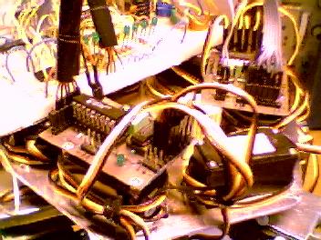
The second suite (v2.0-2.2) is however compatible to that principle. It is still single-sided, but fundamentally redesigned to fit the communication priciple (which was developed at this time). It had more free I/Os and was slightly smaller and (of course) supported the nibble bus. I made two of these to verify that more than one card could be connected to the hub (prototype).
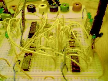
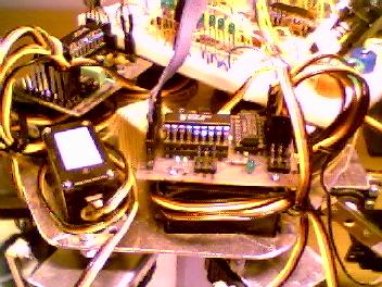
The cards are photographed mounted on-board the robot so you may have some trouble locating them... The close-up should be no problem though. Six servos are connected to each card (black-red-yellow cords). The two cards are connected to the (test) hub via the nibble bus. The bus connections are the flat cables.
 |
 |
 |
 |
The third suite (v2.3-) is closing in to what will be the final design. This card is double-sided and is manufactered by a PCB company ESTEK AB (I got tired of all the work with PCB manufacturing at home...). On the robot two of my hand-made cards, and one factory-made will be present. All soldering et c was still made by me.
Servo PCB v2.4 was finally produced and below are pictures of both non-assembled PCBs and PCBs assembled & mounted on the robot.
 |
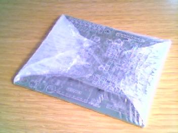
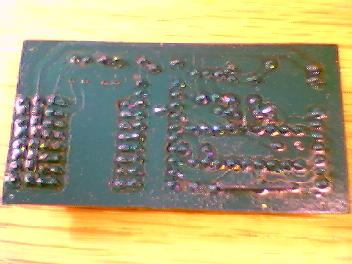
Well, in the beginning I manufactured all PCBs myself by hand: I used a special plastic sheet and printed the PCB layout directly on it with a standard laser printer. Then I heated a metal mini-anvil to approx 225 degrees Centigrade and pressed the black carbon screen onto the copper layer on the PCBS. After touching up the layout with a black permanent ink pen, I etched PCB copper in an etching fluid.
After this the board had to be cleaned and measured for connectivity. Usually the traces weren't very neat, but it worked.
Next thing to do was drilling. I used a mini drilling-maching (Dremel). First I carefully marked each hole by hand with an awl and a hammer.
Of course this is a delicate and cumbersome procedure, especially when the boards become denser. So after I convinced myself that I actually could manufacture PCBs myself, I decided to skip this step for the hub PCBs and leave it to the professionals. The hub had to be at least double-sided, so it should have been quite difficult to manufacture it with the method described here.
I handed my layouts to the guys at ESTEK AB and they did an excellent job!