
|
|
I've kept the mechanics fairly simple, but nevertheless it took quite some time to manufacture the stuff and calibrate it. I wanted high mechanical precision without requiring too advanced tools or materials. In order to make all six legs "identical" I constructed a simple fixture from plywood, a drawing and some nails. It was important to calibrate the angles thoroughly in order to make the mechanical axes and angles adapted to their mathematical counterparts.
The approach was to build the robot small and light. A standard RC-servo has a typical torque of 3kg/cm. If a stretched leg is let's say 15cm, the servo can support only 200g.
The body must also be stiff enough to not flex as this will degrade the mechanical precision of the foot positions. Even if it's possible to compensate for in software, it's still desirable to avoid flexing as much as possible.
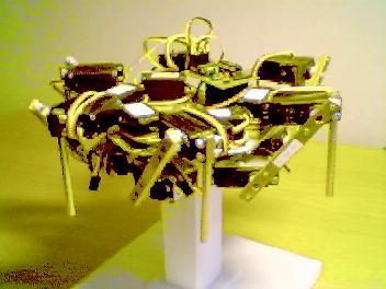
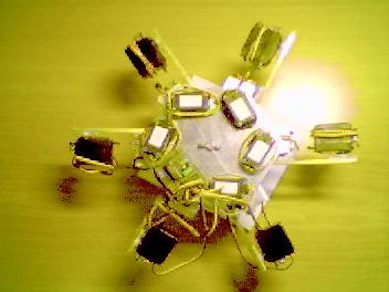
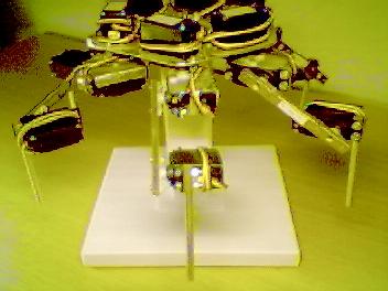
The body is made of an aluminium plate shaped as a hexagon. Another, more advanced, material could have been a very light but yet stiff carbon fibre plate, but I used aluminium to start with.
 |
 |
 |
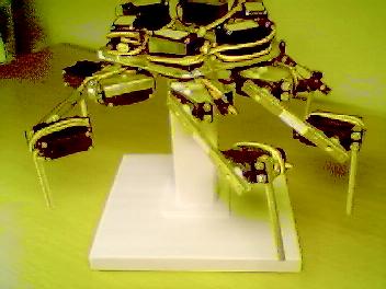
The legs are symmetrically distributed on each corner. On each corner of the hexagon I drilled/sawed out the holes for each hip servo. The servos are mounted with ordinary bolts and nuts (it's heavy but flexible - I can easily disassembly the entire robot and replace faulty units or reuse them on future projects.).
In order to calibrate the servo angles I made the holes slightly larger than the servo casing.
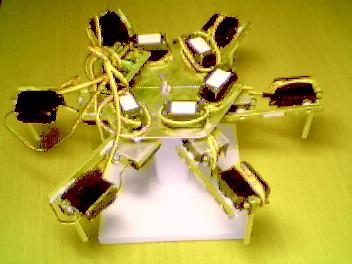
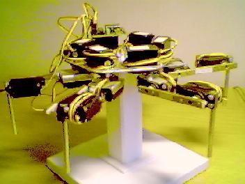
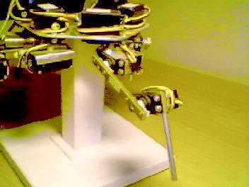
To be able to work on and experiment with the robot I built a stand for it. The stand is a wooden rod connected to the body plate's under side. This allows the robot to "dry walk" with the legs in the air.
The six legs are built directly upon the servos to keep the weight down and the mechanical complexity low. Since the load on each servo axis won't be very high (or et least not applied very often) I built no framework at all. The servo cases themselves are supporting parts of the legs.
 |
 |
The first hip joint servo (closest to the body and rotating around a vertical axis) is bolted directly to the body plate.
 |
 |
 |
The second hip joint servo (rotating around a horizontal axis) is connected directly to the first through a special aluminium casing in which the servo is fitted and fastened with bolts an nuts. The servo is attached directly to the first servo's axis.
 |
 |
 |
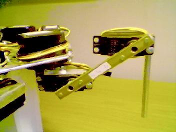
The knee servo (rotating around a horizontal axis) is connected to the second hip servo with a hollow brass rod with a small piece of wooden rod inserted in each end for support. I'd rather use aluminium here too, but I couldn't get any suitable sizes. This is the upper actuator.
 |
|
 |
Finally the lower actuator is attached directly to the knee servo and is made of an aluminiun pipe. Currently there are no feet, so the poor droid has to walk on it's bone pipes...
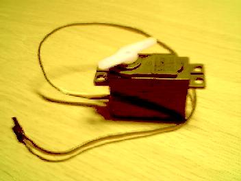
Not much to say, I use standard, pretty cheap, RC-servos from Hitech (HS-303). The torque is about 3kg/cm (which is too little), and the nominal angle span is about 100 degrees but I think it can be electronically pushed over the limits to make the robot even more lithe (haven't tried it and there is no need..)
 |